AVC-R Electronic Boost Controller
Install On A Nissan 200sx S14a


- Battery Drill
- Philips Bit For Drill
- 6 x Self Tapping Screws
- Philips Head Screwdriver
- 10 mm& 8 mm Sockets
- 10 mm& 8 mm Ring Spanners
- Soldiering Iron
- Solder
- Electrical Tape
- Cable Ties Various Sizes
- Small Flat Head Screwdriver
- Lay Out Parts
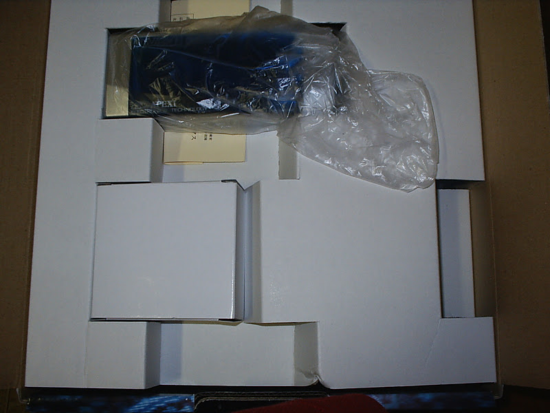
OK so you have got the nice shinny new box with the avc-r in it.
Once u have finished admiring it from various angles you should open it up.

The best thing to do when starting this is to lay out all the parts and have the wiring diagrams and install stuff ready to go.
Lay out all the parts and check the documentation that came with the AVC-Rfor the one that has pictures of the parts.
Check that they are all there.


STEP 1
Disconnect Battery
Pretty self explanatory that one. Must do this before starting anything
STEP 2
Laying Out Wires
OK so start to lay out the wires in you engine bay and see where everything goes.
You are going to have to punch the wire that connects to the control module and also the one that wires up to the ECU through the fire wall.
I chose the hole where the factory wires go through to the ECU. Pull back the large rubber grommet and feed the wires through, you may have a bit of trouble getting it through the first time but keep trying and you will get it. If you find that the wire has not gone through but you have pushed the wires in then more then likely the wires have gone into the fire wall between the metal and the insulation, if this happens pull it back out and try again as other wise you will have to cut the rubber in your passenger foot well to get the wires through.

STEP 3
ECU Wiring
OK now this is where we get down and dirty.
Start by pulling off the black kick panel to the left of the passenger side footwell to expose the ECU.
Now u will notice that there is a cover on the plug, remove this with a small flat head screwdriver then you will notice that the ECU is held on by a bolt (10 mm) remove this so as you can free the plug. Once you have removed the plug from the ECU. you can start to examine all the wires.
Now this is where u go and grab the wiring diagram for the ECU (remember I told u to have this handy).
Once you have the diagram work from the right hand side (the side that was all the wires are facing) and bear back the wires that u need to do.
ECU. WIRING DIAGRAM FOR S14a (Other Ones Are Different)
S14a Wiring Diagram.pdf 
AVC-R WIRING COLORS
You want to strip back the wires about 2-3inchs back from the connector as this will give you enough room to patch up if you make a mistake, and also room to make a good solder joint.
Once you have done each joint cover it with a piece of electrical tape.
AVC-R WIRE COLOR to ECU. WIRE COLOR
GREEN & BLACK WIRE to BLACK With WHITE STRIPE - GROUND
RED WIRE to BLACK With THICK WHITE STRIPE - IG POWER
WHITE WIRE to WHITE - SPEED SIGNAL
GRAY WIRE to YELLOW WITH GREEN or BLUE STRIP - THROTTLE SIGNAL
PURPLE WIRE to BLUE WIRE - RPM SIGNIAL


STEP 4
Installing Boost Solenoid
Now that you have placed the wires all out and wired up the ECU. you are going to have to mount your Boost Solenoid. I choose the spot in front of the passenger side strut tower. There is two plugs here and a nice little flat spot which is an ideal location away from heat etc. If you have something in this spot (Models with Passenger Air Bag or ABS) then remove the factory solenoid and make up a bracket for it to go in there.
The most critical point about mounting the solenoid is that you use the backing rubber that comes in the kit. Apparently the solenoid is very sensitive to vibration and can be easily damaged.
So if we say that you are going to mount it in the spot with the two plugs, remove the plugs and place the rubber backing plate on the flat section. Use this to put four self tapping screw into the metal then remove these and place the Solenoid with the backing plate in the spot and screw the screws down tight (Not too tight just enough to make a firm mounting)


STEP 5
Hooking Up Boost Solenoid
On the solenoid you have two pipes, one that has written above it NO and the other that says COM.
The one that says NO connects up to your intercooler piping, on the blitz LM spec cooler that I have there is a brass elbow that you can run the piping to but you can use the factory piping for this.
The one that says COM connects up to the wastegate. Use the factory hose or if it is not long enough then you can use some of the piping that was supplied with the kit.


STEP 6
Installing Pressure Sensor
Next thing is the pressure sensor. This must be mounted with the top of the sensor upwords, this is very important as aparently it will not work correctly if it is not placed in this manner. I chose the firewall near the VIN plate, this location is away from direct heat and any other opstructions.
Mark the two hole and then pre drill the two hole then screw in the self tappers.


STEP 7
Hooking Up Pressure Sensor
Use the smaller diameter hose that came with the kit and hook it up to the Presure Regulator. This is the small thing in the last shot, you will need to install a T piece in this pipe and the T piece comes with the kit. Now where i located the Presure Sensor on the fire wall the pipe that comes with the Apex kit will not be long enough but you can use some of the larger hose as a temp mesure (mine is still on there after 1 month) and then purchase a longer piece of pipe for this.
Run the piping loosely inbetween the manifold and the engine block and around to the pressure sensor.


STEP 8
Finishing Off
Ok so everything is in and all wired up, double check everything and then re connect the negative terminal back up.
Check everything again then crank the car over, you should see the AVC-R start up with the cool looking APEX logo and then it goes into the menu.
OK stop admiring it and turn off the engine.
Now you can properlly tie off all the wires in the engine bay and then fix up the wires in the loom etc and place all the panels back on.
note - i have not included the install of the actual Comand unit, i think you can work out where you would like to place it for yourself but a word of warning. KEEP IT AWAY FROM PRYING EYES. Or else you won't be the only one admiring you new handy work.
APEXI AVC-R WIRING DIAGRAM & ECU. WIRING
No comments:
Post a Comment